Kamagra enthält Sildenafilcitrat als pharmakologisch aktiven Bestandteil. Dieser hemmt selektiv die Phosphodiesterase-5 und erhöht dadurch die Konzentration von cGMP im Corpus cavernosum. Der Effekt ist zeitlich begrenzt, da die Halbwertszeit von Sildenafil etwa vier Stunden beträgt. In der galenischen Form als Mundgel erfolgt die Resorption besonders rasch, was zu einem schnelleren Wirkeintritt führt. Der Abbau erfolgt überwiegend hepatisch über CYP3A4, wobei ein aktiver Metabolit entsteht, der zur Gesamtwirkung beiträgt. Typische Nebenwirkungen ergeben sich aus der Vasodilatation, darunter leichte Kopfschmerzen und nasale Kongestion. In klinischen Beschreibungen wird kamagra oral jelly im Zusammenhang mit der schnelleren Absorption erwähnt.
Improx (ac) advanced controller
MODEL NUMBER: XAC900-1-0-GB-XX XAC904-1-0-GB-XX
ImproX (AC) Advanced Controller INSTALLATION MANUAL SPECIFICATIONS Working Environment
Designed to work in an indoor (dry) environment similar to IP30. The Controller is, therefore, NOT sealed against water.
Input Voltage Power Requirements Current (mA) Power (W) Installer Interfaces
Back-lighting :
Turned on and off via the Communications Protocol.
Flashing Green LED (internally visible).
INSTALLATION INFORMATION Accessories
Find the following when unpacking the XAC900-1-0-GB-XX (Motherboard ONLY): •
An ImproX AC Controller Motherboard assembly, fitted with two Memory Modules.
Find the following when unpacking the XAC904-1-0-GB-XX: •
An ImproX AC Controller, fitted with two Memory Modules. The ImproX AC is supplied housed in a Black, powder coated, Aluminium extruded Cabinet. The Cabinet will consist of a Top Cover and a Base sealed at each end with a Mild Steel End Plate, secured with 5 Thread Cutter Screws (M3 x 8 mm).
Remember the following when installing your ImproX AC Controller:
CAUTION: DO NOT connect Power Supply cables to Port 1 and Port 2 terminals, as this will cause serious damage to the Controller. Communications Distance
The RS485 communications distance between the ImproX AC Controller and the LAST ImproX Unit in a cable run, MUST NOT exceed 1 km (1 090 yd). Achieve this by using good quality screened twisted 2-pair, twisted pair cable, EARTHED on one side.
Termination Resistors for RS485 Bus Communications
Long transmission lines or multiple “star” connections, may cause communication problems. Placing the Terminating Resistor Jumper Link in the LAST UNIT AT THE END OF THE CABLE RUN should solve the problem (depending on the bus).
EARTH Connection
Connect the ImproX AC Controller to a good EARTH point. Using either of the RS485 Ports, connect the EARTH Lead to the “ETH” Terminal. Mains EARTH can be used, but electrical noise may exist. The EARTH Lead to the ImproX AC Controller should have a minimum cross-sectional area of 1 mm2 (0.001 in2) and can be either solid or stranded.
Blank Space Installing the Battery First Time Use CAUTION: Insert the Battery into the Battery Holder BEFORE powering up the ImproX AC Controller.
The Battery Holder is located in the top left-hand side of the ImproX AC Controllers Printed Circuit Board (PCB), directly below the LCD Ribbon Cable Connector.
Slide the supplied 3 V, CR2032, Lithium cell Battery under the metal clip of the Battery Holder, with the "+" Terminal facing UP.
Pull the plastic clip horizontally AWAY from the Battery Holder and press the Battery firmly into the Battery Holder.
Replacement CAUTION: DO NOT disconnect Power from the ImproX AC Controller during this operation. Disconnecting the Power could result in the RAM loosing data.
With the Controller powered up, remove the Top Cover. DO NOT disconnect the Ribbon Cable Connector.
Remove the Battery from the Battery Holder, by pulling the plastic retaining clip horizontally AWAY from the Battery Holder. The Battery Holder is spring-loaded, and will raise the Battery out of the Holder.
Slide the new 3 V, CR2032, Lithium cell Battery under the metal clip of the Battery Holder, with the "+" Terminal facing UP.
Pull the plastic clip horizontally AWAY from the Battery Holder and press the Battery firmly into the Battery Holder.
Installing Extra Memory Modules (Optional Extra)
Add additional Memory Modules for applications where additional memory is required:
CAUTION: It is very important that the Memory Modules are inserted correctly. Pin 1 as indicated on the Memory Module must correspond with Pin 1 on the ImproX AC Controller.
Remove the power from the ImproX AC Controller.
Remove the Controllers Top Cover and the LCD Display Cover (if installed).
Carefully insert the Memory Modules into the positions JP3 to JP8 as indicated on the ImproX AC Controller.
Re-attach the Controllers Top Cover and if necessary the LCD Display Cover and re-apply power to the Controller.
On power-up a diagnostic test will run on the inserted Memory Modules added to the system. The diagnostic test will display on the LCD Display Cover (if installed).
Mounting the LCD Display (Optional Extra)
Remove the power from the ImproX AC Controller.
Insert the Ribbon Cable Connector from the LCD Display Cover into the Box Header labelled LCD1 on the ImproX AC Controller.
Place the LCD Display Cover over the ImproX AC Controller so that the mounting holes in the Cover align with the securing holes on the Controllers Base.
Secure the LCD Display Cover to the standoffs using the supplied screws, washers and nuts (supplied with XAC903-0-0-GB-XX).
Mounting the Controller
Select the mounting position of the ImproX AC Controller, considering accessibility and routing of wires.
Secure the Controller to the mounting surface, using four suitable screws and wall plugs (supplied), nuts and bolts or rivets.
Blank Space ELECTRICAL CONNECTIONS Connecting the ImproX AC Controller
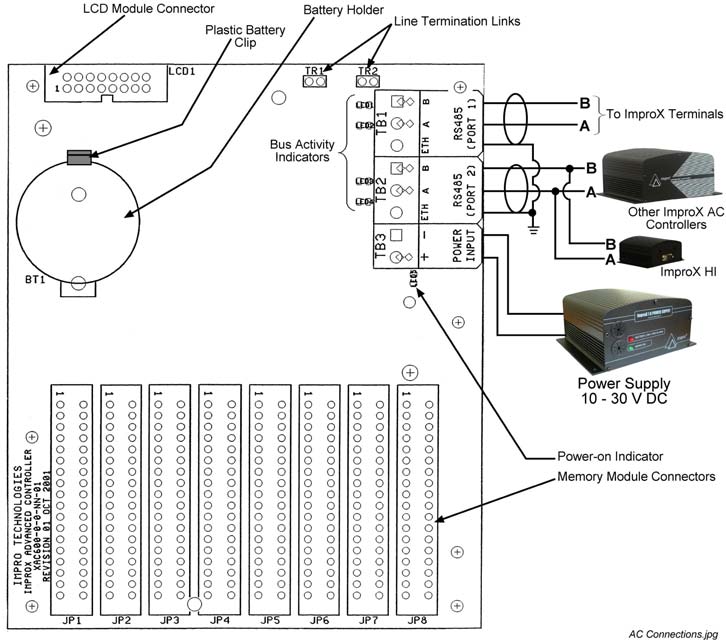
Figure 1 shows various connection options for the ImproX AC Controller.
Figure 1: Typical ImproX AC Electrical Connections Blank Space Power-on Self-test
The Power-on Self-test test the RAM, Flash-ROM checksums and RTC.
The results of the Self-test are made available as diagnostic information via the protocol to the associated Controller or PC.
If any parameter in the Self-test fails, the Controller displays the fault on the LCD Display Cover (if installed).
Fixed Address Label
Once the ImproX AC Controller is installed attach the additional loose Fixed Address Label (packaged with the Controller) in position on the Unit Location Chart. When the system installation is complete and all the units are represented on the Unit Location Chart by their Fixed Address Labels, file the document for future reference.
Unit Location Chart Fixed Address Label Unique Location Description Fixed Address Label Unique Location Description Fixed Address Label Unique Location Description Fixed Address Label Unique Location Description Fixed Address Label Unique Location Description Fixed Address Label Unique Location Description Fixed Address Label Unique Location Description Fixed Address Label Unique Location Description Fixed Address Label Unique Location Description Table 1: Unit Location Chart GUARANTEE OR WARRANTY This product conforms to our Guarantee or Warranty details placed on our Web Site, to read further please go to www.impro.net. USER NOTES USER NOTES USER NOTES
This manual is applicable to the ImproX (AC) Advanced Controller,
XAC900-1-0-GB-01 and XAC904-1-0-GB-01. (The last two digits of the Impro stock
code indicate the issue status of the product).
SPEAK OUT - PUBLIC HEALTH: Suboxone works; it’s a tool we must use Suboxone has made its way to the street and so has methadone, OxyContin, Percocet, neurotin, clonidine, Klonipin, phenergan, elaviland .the list goes on. Some of these drugs stick out and we acknowledge that narcotics and benzo’s are on the street, but do we know that anti-nausea drugs, high-blood-pressure pills, etc., are on
P.O. BOX 8 COLUMBUS CHEMICAL INDUSTRIES INC. COLUMBUS, WISCONSIN 53925-0008 (920) 623-2140 FAX (920) 623-2577 Material Safety Data Sheet U.S. Department of Labor Occupational Safety and Health AdministrationCommunication Standard, 29 CFR 1910 1200. Standardmust be consulted for specific requirements IDENTITY (as Used on Label and List) Note: Blank spaces are not p

 MODEL NUMBER:
  INSTALLATION INFORMATION
  Installing the Battery
  Mounting the LCD Display (Optional Extra)
 ELECTRICAL CONNECTIONS
  Power-on Self-test
  Fixed Address Label
  Fixed Address Label
  Fixed Address Label
  Fixed Address Label
  Fixed Address Label
  Fixed Address Label
  Fixed Address Label
  Fixed Address Label
  USER NOTES
  USER NOTES