Kamagra enthält Sildenafilcitrat als pharmakologisch aktiven Bestandteil. Dieser hemmt selektiv die Phosphodiesterase-5 und erhöht dadurch die Konzentration von cGMP im Corpus cavernosum. Der Effekt ist zeitlich begrenzt, da die Halbwertszeit von Sildenafil etwa vier Stunden beträgt. In der galenischen Form als Mundgel erfolgt die Resorption besonders rasch, was zu einem schnelleren Wirkeintritt führt. Der Abbau erfolgt überwiegend hepatisch über CYP3A4, wobei ein aktiver Metabolit entsteht, der zur Gesamtwirkung beiträgt. Typische Nebenwirkungen ergeben sich aus der Vasodilatation, darunter leichte Kopfschmerzen und nasale Kongestion. In klinischen Beschreibungen wird kamagra oral jelly im Zusammenhang mit der schnelleren Absorption erwähnt.
Microsoft word - 13681-b man-u24.doc
HOBO® U24 Conductivity Logger (Part # U24-001) Inside this package:
The optical interface allows the logger to be offloaded
without breaking the integrity of the seals. The USB
compatibility allows for easy setup and fast downloads.
A light (LED) in the communications window of the
logger confirms logger operation. The following table
explains when the logger blinks during logger operation:
When: The
seconds (the shorter the logging interval, the faster the light blinks).
Description
The HOBO U24 Conductivity logger is ideal for
measuring and monitoring the impacts of pollutants such
as road salt, agricultural runoff, chemical spills, and salt
water intrusion on water supplies and aquatic ecosystems.
Conductivity is a measure of water’s ability to conduct electrical current, which is effected by pollutants,
Sleep Mode
especially those containing inorganic dissolved solids. The purer the water is, the lower the conductivity. Continuous
The logger consumes significantly more power when it is
monitoring of conductivity at multiple sites along a stream
“awake” and connected to a base station or shuttle. The
or in a well will determine when and where spikes of high
logger will go into a low-power (sleep) mode if there has
conductivity occur, with the goal of identifying the sources
been no communication with your computer for 30
of contamination that caused the high conductivity.
minutes. To wake up the logger, remove the logger from the coupler, wait a moment, then re-insert the logger.
Software Sample and Event Logging
The logger can record two types of data: samples and
Communication
events. Samples are the sensor measurements recorded at each logging interval. Events are independent occurrences
To connect the logger to a computer you can use:
triggered by a logger activity, such as Bad Battery or Host
• Optic USB Base Station (BASE-U-4) with a
Connected. Events help you determine what was
• HOBO Waterproof Shuttle (U-DTW-1) with a
The logger stores 64K of data, and can record over 18,500
temperature and conductivity measurements.
To launch and read out the logger in the field you can use one of these methods:
• Laptop computer with Optic USB Base Station
• HOBO Waterproof Shuttle (U-DTW-1) and a
• HOBO U-Shuttle (U-DT-1, Firmware Version
1.12m030 or later) with Optic USB Base Station and coupler (COUPLER2-C).
Connecting the Logger to a Computer or Waterproof Shuttle NOTE: Logging Battery Voltageis not essential since you can check the battery voltage using the STATUS screen at
1. If you are connecting to a computer, follow the
Launch or Readout of the logger. Logging the battery
instructions that came with your base station or
voltage will reduce the number of conductivity and
Waterproof Shuttle to attach it to a USB port on
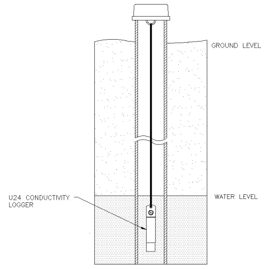
Deploying the HOBO U24
2. Attach the coupler to the base station or shuttle.
3. Insert the logger into the coupler, aligning the
The HOBO U24 is designed to be easy to deploy in many
bump/arrow on the coupler with the arrow on the
environments. The small size of the logger is convenient
logger. Be sure that it is properly seated in the
for use in small wells and allows the logger to be mounted
NOTE: If you are using the HOBO Waterproof Shuttle
as a base station with a computer, briefly press the Coupler Lever to put the shuttle into base station mode.
If the logger has never been connected to the computer before, it may take a few seconds for the new hardware to
Deployment Guidelines
• You will need to use a field conductivity meter to
Important: USB communications may not function
periodically calibrate the U24 readings. Calibrate
properly at temperatures below 0°C (32°F) or above 50°C
the field conductivity meter before taking it into
• Make sure the logger is getting a steady flow of
Before you deploy the HOBO U24 in the field, perform the following steps in the office:
• If possible, when deploying the logger in rivers,
streams and ponds, insert the logger in a PVC or
ABS pipe. The PVC pipe should have enough
2. Connect the logger to the computer. See
holes to ensure good circulation of water.
“Connecting the Logger to a Computer or
• To avoid bubbles collecting on the sensor, make
sure the sensor face is vertical and avoid sudden
Click STATUS on the toolbar and observe that the
• Do not place any metal within 2.5 cm (1”) of the
temperature is near the actual temperature.
4. Launch the logger. See the HOBOware User’s Collecting Data Analyzing the Data Initial Deployment at Each Site
1. Offload the most recent data files from the shuttle.
1. Launch the logger with a laptop or shuttle.
3. Calibrate data and convert to specific conductance
3. Allow enough time for the logger to temperature
stabilize for the best accuracy (approximately 15
Conductivity Assistant to calibrate the readings and adjust for drift caused by fouling. You will
4. Gently tap the logger to remove any bubbles from
need to enter the field meter readings and times
the surface. Tug the string if you cannot reach the
from the beginning and, optionally, the end of that
5. Measure the specific conductivity, referenced to
Refer to the Help for the Conductivity Assistant
25°C, with the field meter. Record the value, time
and location of that reading in a field notebook. If you cannot access the water with the meter, use a
Maintenance
bailer or other device to obtain a water sample.
Cleaning the Sensor
Repeat procedure for each logger deployed.
Mix several drops of dish detergent or biodegradable soap
Field Readout
in a cup of tap water with a clean cotton swab. Clean the sensor face using the cotton swab and then rinse the sensor
Your readout and maintenance schedule will be
with clean or distilled water. Do not scratch the sensor face
determined by the amount of fouling at the site.
1. Calibrate the field conductivity meter before using
Biofouling
Biofouling and excessive marine growth on the logger will
2. Before removing the logger, measure the specific
compromise accuracy. Organisms that grow on the sensor
conductivity with the field meter. Record the
can interfere with the sensor’s operation and eventually
value, time and location of that reading in a field
make the sensor unusable. If the deployment area is prone
to biofouling, check the logger periodically for marine
3. Remove the U24 logger from the stream.
4. Read out the data from the logger using a shuttle.
Solvents
Check a materials-compatibility chart before deploying the logger in locations where untested solvents are present.
Refer to the Specifications for materials.
Protecting the Logger
8. Allow enough time for the logger to temperature
IMPORTANT
9. Gently tap the logger to remove any bubbles from
• This logger can be damaged by shock.
the surface. Tug the string if you cannot reach the
Always handle the logger with care. The logger
may be damaged if it is dropped. Use proper
10. Measure the conductivity with the field meter.
packaging when transporting or shipping the
Record the value and time of that reading in the
• Do not attempt to open the logger case or sensor
WARNING: Do not cut open, incinerate, heat above
100°C (212°F), or recharge the lithium battery. The battery
Disassembling of the logger case or sensor
may explode if the logger is exposed to extreme heat or
housing may cause serious damage to the sensor
conditions that could damage or destroy the battery case.
and logger electronics. There are no user-
Do not dispose of the logger or battery in fire. Do not
serviceable parts inside the case. Contact Onset
expose the contents of the battery to water. Dispose of the
technical support if your logger requires servicing.
battery according to local regulations for lithium batteries.
Specifications Conductivity Temperature
Low Range: 0 to 1,000 µS/cm 5° to 40°C (41° to Full Range: 0 to
The Battery Battery Life
The battery life of the logger should be three years or
more. Actual battery life is a function of the number of
deployments, logging interval, and operation/storage
temperature of the logger. Frequent deployments with
logging intervals of less than one minute, and continuous
storage/operation at temperatures above 35°C, will result
conductivity ranges (64kbytes total memory)
in significantly lower battery life. For example, continuous
1 second to 18 hrs, fixed or multiple-rate
logging at a one-second logging interval will result in a
battery life of approximately one month.
To obtain a three-year battery life, a logging interval of
one minute or greater should be used and the logger should
be operated and stored at temperatures between 0° and
0° to 50°C (32° to 122°F) - non freezing
Battery Voltage
The logger can report and log its battery voltage. If the
mounting hole (1.25" diameter x 6.5", ¼”
battery falls below 3.1 V, the logger will record a “bad
battery” event in the datafile. If the datafile contains “bad
battery” events, or if logged battery voltage repeatedly
falls below 3.3 V, the battery is failing and the logger
The CE Marking identifies this product as
should be returned to Onset for battery replacement.
complying with all relevant directives in the European Union (EU).
Replacing the Battery
2010 Onset Computer Corporation. All rights reserved.
To have your logger’s battery replaced, contact Onset or
Onset, HOBO, and HOBOware are trademarks or registered trademarks
your place of purchase for return arrangements. Do not
of Onset Computer Corporation covering its data logger products and
attempt to replace the battery yourself. Severe damage to
the logger will result if the case is opened without special
All other trademarks are the property of their respective companies.
Volume 12, Issue 3 The San Diego Association for Rational Inquiry Newsletter Summer, 2007 Does Rational Thought years lauded the moderator who Exclude Faith? faith, or hypocritical claim of it, is every candidate who claims a bit considered unfair, even if faith is of validity because of his relig-encouragement of One seldom hears the words used as a reason to shape foreign
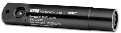 HOBO® U24 Conductivity Logger
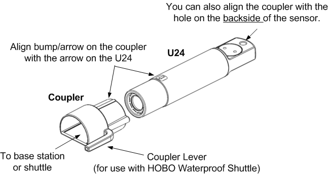
 Connecting the Logger to a Computer
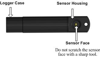

 • Do not attempt to open the logger case or sensor
WARNING: Do not cut open, incinerate, heat above
• Do not attempt to open the logger case or sensor
WARNING: Do not cut open, incinerate, heat above